IV. INSTALLATION

General Information
For the highest heat transfer, connect the unit so that a counter-current flow is obtained.
Installation
Figure 5 shows the installation of an evaporator. For evaporators connect the refrigerant to the side with the soldered connections (S3, S4) so that it enter the unit at the bottom. The expansion device should be positioned not less than 150-200 mm from the connection (S3). Bent tubes and elbows between the expansion device and the connection should be avoided. Connect the liquid to that side of the BHE that best suits your installation (Sl, S2) or (Tl, T2).
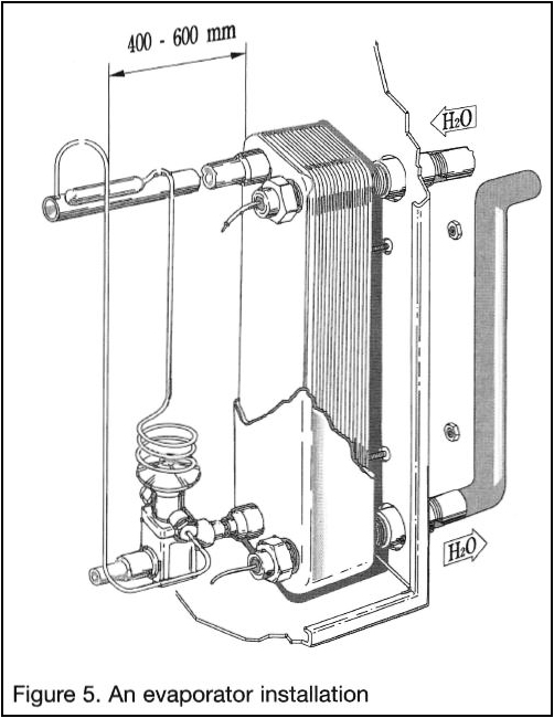
NOTE: Units with the option of the real double circuit have a single water circuit with connections in a central position and two independent refrigerant circuits. The refrigerant circuits, unless otherwise indicated, have diagonal flow. The refrigerant side connections follow the normal rules with the additional note of being diagonally opposite.
Mounting
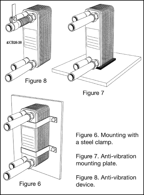
Always mount the unit vertically in two phase applications. For single-phase applications the BHE can be mounted horizon tally or vertically without affecting the function.
Units smaller than CB30 can be mounted directly on the pipes. Mount larger units on anti-vibration plates or fasten with steel clamps (Figure 6 or 7) or bolts, when included. If there is risk of vibrations, use an anti-vibration device as in Figure 8. Models with HX, MX, LX plate configurations or model AC must not be installed upside down. The tightening torque for the 5/16″ bolts is 90-105 in-lb; for the 3/8″, it is 195-221 in-lb. For larger sizes of units, removable feet and lifting lugs can be provided as an option.
Threaded Connections
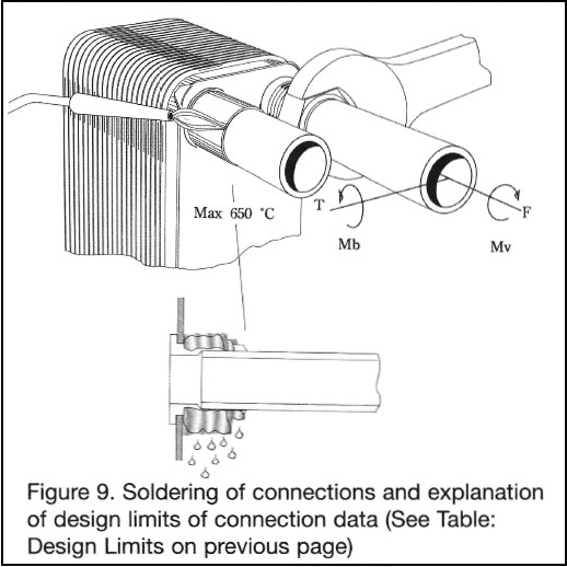
Connect the pipe using a dynamometric wrench respecting the indicated limits. The limits are measured on the largest diameters. In case of the smaller connections, the torque is lower. In the AC units, the Victaulic type connection can be supplied.
To avoid damaging the threaded connections, it is important to mount the BHE on the pipes within the recommended design limits. (See Figure 9).
Soldered and Welded Connections
The temperature must not exceed the melting point of the brazing material. Use a wet towel around the connection and the plate pack to reduce the heat transferred to the BHE plate pack during installation.
Filling material: 30-55% silver alloy Flux material: Black Flux for silver soldering:
- Clean the soldering assembly surface at the copper tubes and BHE connections.
Remove oil or other build-up with degreasing solvent
Polish the surfaces to remove oxides - Apply the flux to the surface with a brush to remove and prevent oxidation.
- For refrigeration installations, use a dry Nitrogen gas on the refrigerant side to prevent oxidation
- Heat the soldering area to the soldering temperature of about 1200(F. (Higher temperatures will melt the brazing material.) Use a wet cloth to minimize the heating zone.
- Keep the tube in a fixed position and add the filler material.
Welding
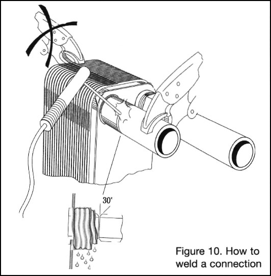
- Prepare the edge of the tube for welding with a 30° bevel.
- Place the piping into the connection.
- TIC-weld or MIG-weld the tube to the connection, filling the groove formed by the two edges. This method minimizes the heating zone.
WARNING: Unnecessary heating (above 1200 (F) can melt the brazing material!
V. REGULATION
The efficient design of plate heat exchangers allows the total hold-up volume of the system (pumps, valves, piping and controls) to be much smaller than that of systems using conventional heat exchangers. This high efficiency results in a quick response time. The valve and regulation equipment should be designed accordingly.
The valve with the shortest response time should be placed close to the outlet. This will give a faster response when there is a small load. Follow the instructions from the valve manufacturer and if possible, use a PI regulator with a logarithmic response. This is especially recommended in steam applications.
Excessive cycling amplitude of pressure and temperature can lead to leakage after some time as a result of fatigue phenomena. Thermal dynamic stresses are caused by large fast temperature changes (more than 50° F) and can damage the BHE. An ON/OFF valve that causes pressure pulsation in the BHE must be avoided. To minimize thermal fatigue, it is especially important to avoid pressure and temperature pulsations in steam applications or changes in the condensate level inside the steam condenser.
VI. OPERATION
A liquid in motion in a pipe system generates a high level of energy. When a valve is closed or opened, causing the fluid to stop or continue, it must be done slowly to avoid shocking the system.
WARNING: Do not use fast-closing valves unless the pipes of the system are very short!
Start Up
Note: Consult equipment manufacturer’s start up procedures for refrigeration applications.
- Before starting any pump, consult system instructions to determine which pump should be started first.
- Make sure the control valve between the pump and the unit is closed.
- If there is a valve at the exit, make sure it is completely open.
- Open the vent.
- Open the valve SLOWLY.
- Close the valve after all of the air is let out.
- Repeat procedure for the other side of the heat exchanger.
Unit in Operation
If an adjustment to the flow rate is required to maintain correct temperatures or pressure drops, it must be made slowly to prevent shocks to the system. Changes in the performance of the heat exchanger may be caused by a change in: temperature conditions, media flow rates, or fouling.
Shut Down
- Consult system instructions to determine which pump should be stopped first.
- SLOWLY, close the valve controlling the flow rate of the pump being stopped.
- When the valve is closed, stop the pump.
- Repeat for the other side.
- If for any reason the heat exchanger is shut down for a long period, it should be drained. If the media processed is corrosive, contains particles, or has a tendency to coagulate, it is recommended that the heat exchanger be rinsed with water and dried to avoid damage.
![]()
![]()